
Why Build Your Own Temperature Transmitter?
Commercial temperature transmitters cost $100+, but a DIY version gives you full control over specifications while teaching core electronics principles. Unlike pre-built units, you can customize:
Key Advantages of DIY Approach
- Cost savings: 75% cheaper than commercial alternatives
- Custom range: Monitor from -40°C to 150°C based on sensor choice
- Open integration: Connect to Raspberry Pi, Arduino, or home automation systems
- Educational value: Understand signal conditioning and calibration firsthand
Essential Components Breakdown
You'll need these core parts. All components are available from major electronics retailers:
| Component | Key Specifications | Cost-Saving Tip |
|---|---|---|
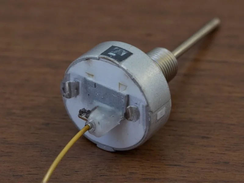
| DS18B20 Sensor | -55°C to 125°C range, ±0.5°C accuracy | Buy waterproof version for outdoor use |
| ESP32 Microcontroller | Wi-Fi/BLE, 36 GPIO pins, 240MHz processor | Use ESP8266 for basic projects ($3 savings) |
| 4-20mA Transmitter IC | XTR111 or RC420 chip | RC420 handles lower voltages better |
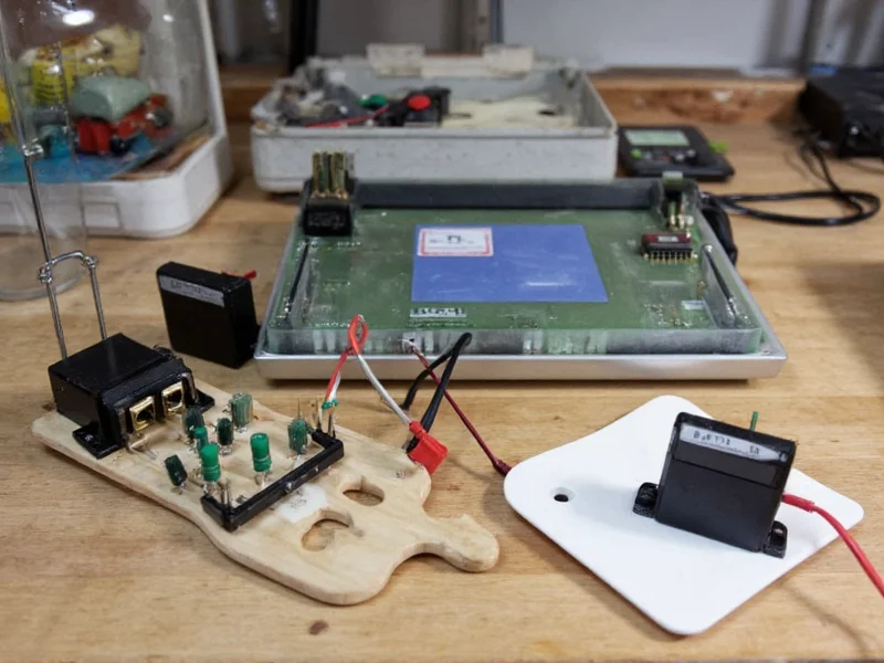
Step-by-Step Assembly Guide
Follow this proven workflow. Total build time: 90 minutes.
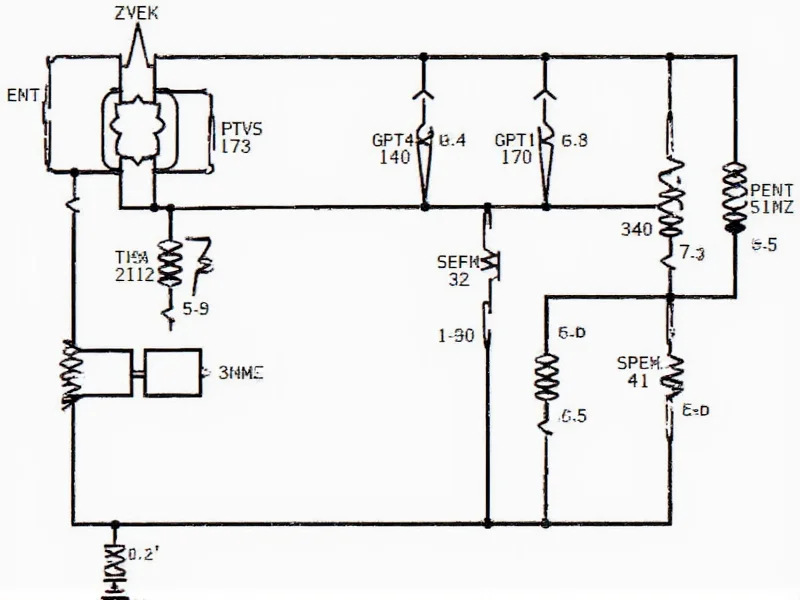
- Circuit Design: Connect DS18B20 to ESP32's GPIO4 with 4.7kΩ pull-up resistor. Verify wiring with multimeter before power-on.
- Signal Conditioning: Use RC420 IC to convert 0-3.3V sensor output to industrial 4-20mA standard. Critical: Add 250Ω load resistor at receiver end.
- Enclosure Prep: Drill 3mm hole for sensor cable in waterproof project box. Seal with silicone grommet to prevent moisture ingress.
- Firmware Setup: Flash ESP32 with this optimized code snippet:
\n#include
    \n#include

     \n#define ONE_WIRE_BUS 4\nOneWire oneWire(ONE_WIRE_BUS);\nDallasTemperature sensors(&oneWire);\nvoid setup() { sensors.begin(); }\nvoid loop() {\n  sensors.requestTemperatures();\n  float tempC = sensors.getTempCByIndex(0);\n  int mA = map(tempC, 0, 100, 400, 2000); // Scale to 4-20mA\n  analogWrite(25, mA); // Output via DAC pin\n  delay(2000);\n}
Calibration: The Critical Step Everyone Skips
Factory sensors have 2% variance. Achieve lab-grade accuracy with this 3-point calibration:
Calibration Protocol
- Place sensor in ice bath (0°C reference)
- Record output value, adjust offset in code
- Test in boiling water (100°C at sea level)
- Calculate slope correction factor
- Verify at room temperature (25°C)
Pro Tip: Use NIST-traceable thermometer for reference. Most DIY projects skip step 3, causing 5°C+ errors at temperature extremes.
Troubleshooting Common Issues
Resolve these frequent problems:
- Signal drift: Caused by unregulated power supply. Solution: Add 100μF capacitor across VCC/GND.
- 4-20mA range error: Check load resistor value. Must be exactly 250Ω for proper scaling.
- Wireless disconnects: ESP32 overheats in enclosures. Add thermal pad between chip and metal box.
Real-World Applications
Deploy your transmitter in these scenarios:
Practical Use Cases
- Home Brewing: Monitor fermentation tanks between 18-22°C
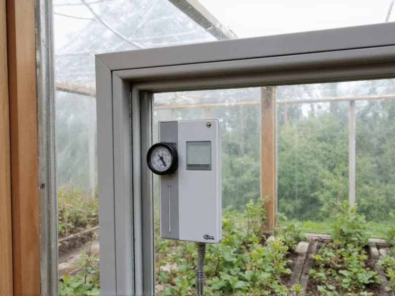
- Greenhouse Control: Trigger vents when exceeding 28°C threshold
- HVAC Maintenance: Detect failing heat exchangers through temperature differentials
For industrial settings, add IP67 enclosure and redundant power. Never use DIY transmitters for life-critical systems.
Final Verification Checklist
Before deployment, confirm:
- Stable readings across 0-100°C range
- No signal drop during 24-hour continuous operation
- Enclosure maintains IP65 rating after sealing
- Calibration verified against certified thermometer
Frequently Asked Questions
Can I use this for food safety monitoring?
Only for non-critical applications like refrigerator monitoring. For HACCP compliance, use certified commercial transmitters with NIST traceability.
How far can the signal travel?
4-20mA signals work up to 1,000 meters with proper twisted-pair cabling. For longer distances, add signal repeaters every 300 meters.
Why choose 4-20mA over digital signals?
4-20mA provides noise immunity in industrial environments and allows loop-powered operation. Digital signals like Modbus are better for multi-sensor networks.
Can I connect to existing PLC systems?
Yes, most PLCs accept 4-20mA inputs. Verify your PLC's input impedance matches the transmitter's load requirements (typically 250-600Ω).


 浙公网安备
33010002000092号
浙公网安备
33010002000092号 浙B2-20120091-4